
In this era of Internal combustion engines this blog post brings you a sneak at external types and also our trails in building one. This will be regularly updated based on our completion of the work. Aim is to build a small Stirling Engine which is small but powerful enough to power a RC car. Lets take a look at the Stirling cycle


It consists of four thermodynamic processes acting on the working fluid. Let us take a look at the β type Stirling engine, the one we are planning to build so that it can be analyzed along with the cycle.
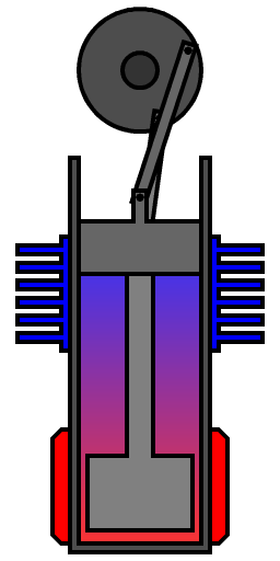
This is how basically the β Stirling engine works. The red colored part is the heated part blue is the heat sink. Observe that the working fluid unlike Internal combustion engines isn't changed every cycle but is the same every cycle. The engine has two pistons the one at the far end that encloses the gas is simply referred to as piston throughout the article. The other one inside will be referred to as displacer piston.
1.Constant volume Heat addition ( aka Isovolumetric or Isochoric Heat addition)
Here the piston has compressed the gas and the displacer piston is also at the far end the gas absorbs the heat from the heat source and expands. This displaces the piston to the towards highest point, leading to isothermal expansion.
2.Isothermal Expansion
This is also called power stroke. The piston is pushed to the farthest end. Note that the displacer piston is already moving downwards.
3.Constant volume Heat removal ( aka Isovolumetric or Isochoric Heat removal)
The displacer piston finally hits the bottom. This results in displacement of gas to the other end cooler part). The heat sink there reduces the temperature of the gas thus resulting in its contraction.
4. Isothermal Compression
This leads to the gas contraction aided by the flywheel momentum causing the piston to fall back. And then again back to Constant volume Heat addition process.
The 3D working model would look somewhat like this
The one we will be trying to build will look similar to this.
Plan
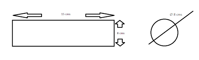
Start with a metal (steel or aluminium) cylinder 15 cms long

Cut the part as shown below using a lathe.

Machine out the extruding 5 cm length to get a heat sink as shown below.

Drill a ∅ 5 cm bore from end A 14 cms deep.

This gives us the cylinder. The piston, displacer, camshaft and flywheel are yet to be designed. For piston we plan to use a cylinder 2 cms long and ∅ 5 cms such that it fits in perfectly. This must house a bore and a pole at one side of it.

Displacer piston must be of ∅ 4.5 cms.
No comments:
Post a Comment